|
|
|
Modeling and UMLUML (Unified Modeling Language) is a graphical notation used to express the analysis and design of a software project and communicate it to others. UML is language independent, but it's intended to describe object-oriented projects. As the creators of UML stress, it is not itself a methodology; it can be used as a descriptive tool no matter what your preferred design process. My goal is to look at UML diagrams from the perspective of a Delphi programmer using ModelMaker. An in-depth discussion of UML is well beyond the scope of this chapter.
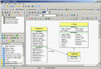
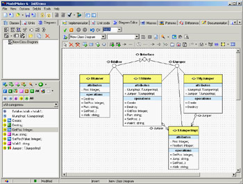
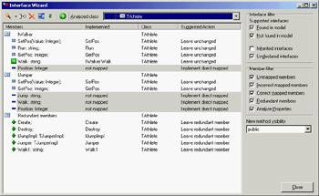
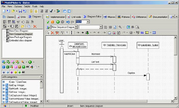
Class DiagramsOne of the most common UML diagrams supported by ModelMaker is the class diagram. Class diagrams can display a wide variety of class relationships, but at its simplest this type of diagram depicts a set of classes or objects and the static relationships between them. For example, Figure 11.1 is a class diagram containing the classes from the NewDate program presented in Chapter 2, "The Delphi Programming Language." If the results are different when you import these classes into ModelMaker and create your own class diagram, keep in mind the numerous options I discussed earlier. Many settings control how your visualized classes will appear. You can open the ModelMaker file (MPB file) used for Figure 11.1 from the corresponding source code folder of the current chapter. Earlier, I mentioned that the ModelMaker diagram editor is just another view into the internal model. Some of the symbols in the ModelMaker diagrams map directly to code model elements, and others do not. With low-level diagrams like class diagrams, most symbols represent actual code model elements. Manipulating these symbols can change the code generated by ModelMaker. At the opposite end of the spectrum, in use case diagrams most (if not all) symbols have no representation within the code model. In your class diagram, you can add new classes, interfaces, fields, properties, and even documentation to the model. Likewise, you can change the inheritance of a class in the model from within the diagram. At the same time, you can add several symbols to a class diagram that have no logical representation within the code model. Class diagrams in ModelMaker also allow you to code to interfaces, thus working at a higher abstraction level. Figure 11.2 shows the relationships of the classes and interfaces in a complex example of interface use, IntfDemo. This example is covered in an online book discussed in Appendix C, "Free Companion Books on Delphi," and is available among the chapter's source code examples. When you're using interfaces in class diagrams, you can specify interface implementation relationships between classes and interfaces, and those implementations will be added to the code model. Adding an interface implementation within a diagram results in the appearance of one of ModelMaker's niftier features: the Interface Wizard (see Figure 11.3). Activating the Interface Wizard for a class greatly simplifies the task of implementing an interface. The wizard enumerates the methods and properties a class needs in order to implement a given interface (or interfaces); if told to, the wizard will add those needed members to the implementing class. Note that it is up to you to provide meaningful code for any methods added to the class. In Figure 11.3, the wizard is evaluating TAthlete for its implementation of IWalker and IJumper and suggesting the changes that are necessary for correct implementation of these interfaces. Sequence DiagramsSequence diagrams model object interaction by rendering objects and the messages that pass between them over time. In a typical sequence diagram, the objects interacting within a system are arrayed along the x-axis, and time is represented as passing from top to bottom along the y-axis. Messages are represented as arrows between objects. You can see an example of a rather trivial sequence diagram in Figure 11.4. Sequence diagrams can be created at various levels of abstraction, allowing you to represent high-level system interaction involving just a few messages or low-level interaction with many messages. Along with class diagrams, sequence diagrams are among the UML diagrams supported by ModelMaker that are most closely related to your code model. You can create several diagrams in ModelMaker in which the diagram symbols have no direct relation to your code model, but in sequence diagramming, you can directly affect the code as you model classes and their methods. For example, as you create a symbol for a message between objects, you can choose from a list of methods belonging to the recipient object; or, you can choose to add a new method to the object, and that new method will be added to the code model. Note that, as mentioned earlier, ModelMaker will not automatically create sequence diagrams from your imported code; you will need to create them yourself. Use Cases and Other DiagramsI've discussed two of the lowest-level UML diagrams first, but ModelMaker supports several other higher-level UML diagrams designed to provide a path from the highest-level user interaction modeling of use case diagrams to low-level class and sequence diagrams. Use case diagrams are among the most-used diagrams, in spite of the fact that their symbols bear no relation to code model elements. These diagrams are intended to model what the software is supposed to do, and they are self-explanatory enough to use in analysis sessions with non-developers. A simple use case diagram consists of actors (users or application subsystems) and use cases (things the actors do). One of the most frequent questions regarding use cases is how to handle use case texts in ModelMaker. Texts for use cases are a typical next step when doing preliminary analysis. For example, a use case is a short description of an action an actor might take ("Preview Sales Report" or "Resize Window"); a use case text is a longer, more detailed description of the text. ModelMaker does not specifically support the longer use case texts; you can either use an annotation symbol within the diagram attached to the use case symbol, or you can link the use case symbol to an external file containing the use case text. You'll learn more about these techniques in the "Common Diagram Elements" section of this chapter. The other UML diagrams supported by ModelMaker are as follows:
Non-UML DiagramsModelMaker supports three diagrams that are not UML-standard, but are quite useful:
Common Diagram ElementsEach type of diagram supported by ModelMaker contains symbols specific to that diagram type, but there are elements within the Diagram Editor that are common to all diagram types. You can add images and shapes to your diagrams, as well as package symbols (containers to which you can add other symbols). The Hyperlink symbol lets you add to a diagram a label linked to some other entity. In fact, the vast majority of diagram symbols support this hyperlinking feature. You can link to another diagram (clicking the link will open the linked diagram in the editor), you can link to an element within the code model (be it class, unit, method, interface, and so on—clicking this link will open the appropriate editor for the linked element), or you can link to an external document (this link will open the linked document with the appropriate application). Three different types of annotation tools are available to each diagram type. Several documents more fully explain these tools, so suffice it to say here that you can add a stand-alone annotation symbol; you can add an annotation symbol that automatically displays the linked object's internal documentation; or you can add an annotation symbol, type in your text, and link this symbol to an object. When you do this, the object's internal documentation is updated to match the annotation symbol's text. Relationship or association symbols default to straight lines. However, you can turn them into orthogonal lines by selecting the symbol and pressing Ctrl+O. You can also add nodes to these symbols by pressing Ctrl and clicking the line. ModelMaker attempts to keep these symbols orthogonal when at all possible. ModelMaker also offers a robust set of visual symbol styles. You can define font and color styles in a hierarchical manner and apply them by name to your diagram symbols. See the entry "style manager" in the online help for more information. One final common feature to note is the ability to hierarchically order the Diagrams list (see Figure 11.5). You can add folders for organizational purposes and to "re-parent" diagrams; to do so, Ctrl+drag a diagram to its new parent. ModelMaker's diagramming capabilities encompass a vast set of possibilities; once you've put some time into learning the feature set, you may find that it transforms your development process. For the Delphi developer, the two-way active nature of the Diagram Editor provides a far more dynamic diagramming experience than most UML editors that simply generate static "pretty pictures." |
|
||||||||||||||||||||||||||||||||||||||||||||||||||||||||||||||||||||||||||||||||||||||||||||||||||||||||||||||||||||||||||||||||||||||||||||||||||||||||||||||||||||||||||||||||||||||||
|